IF
YOU GOT HERE VIA A SEARCH ENGINE THIS WILL TAKE YOU TO THE WAGNER HOME,
This will take you to Page 1
Building a Mauser
Match Rifle - Page 4
The stock was set aside for some "aging" and the scope mount was fitted to the rifle. Once again, follow in these footsteps after careful consideration! There are tens of thousands, maybe hundreds of thousands of rifles fitted with scopes that are held on with 3 or 4 No. 6x48 screws. The Redfield mount comes with these screws. But they look awfully small to me, so I use No.8 screws. This requires modifying the mount as follows.
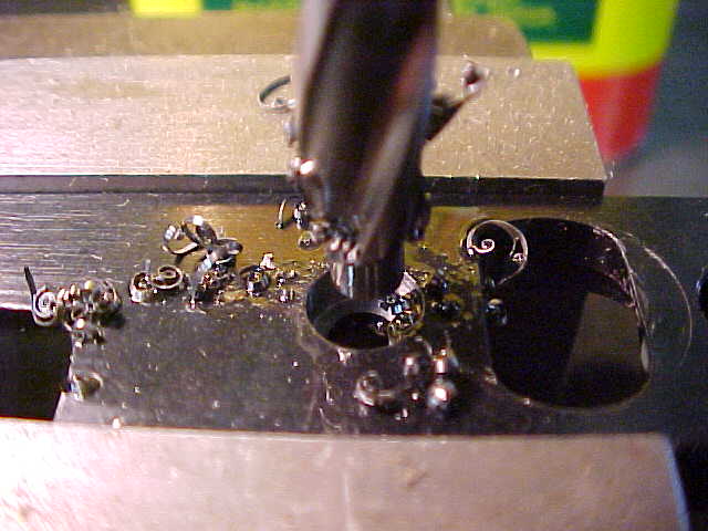
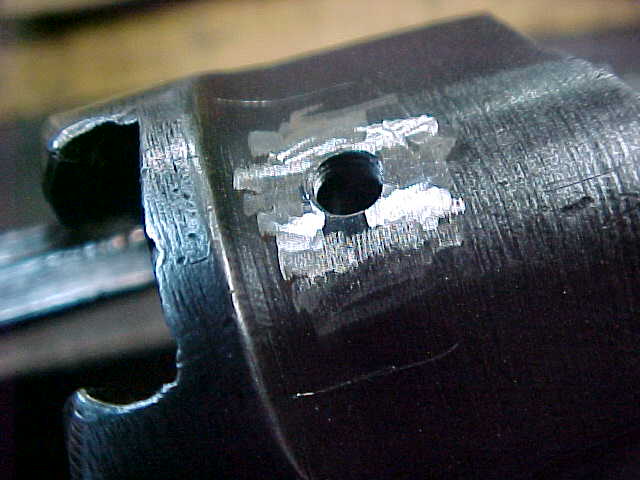
First, the mount is held true on the drill press table and the counter bores enlarged. NOT THE THROUGH HOLES, just the enlarged recess that receives the screw head. This is done with a garden variety No. 6 Cap Screw Counterbore. That is not a typo, I am installing a No.8 screw from Brownells, but using a counterbore designed for a No. 6 Socket (Allen) Head Machine screw. After the recess is enlarged, the through hole is enlarged with a No. 19 drill.
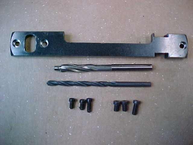
This is the modified mount, the No. 6 counterbore, a # 19 drill and on the left, the # 6 Screws and on the right the # 8 screws.
The modified mount was fitted to the receiver using only the two screws at the front ring, the rear screw being omitted. This revealed that the rear of the mount was sort of floating above the receiver.
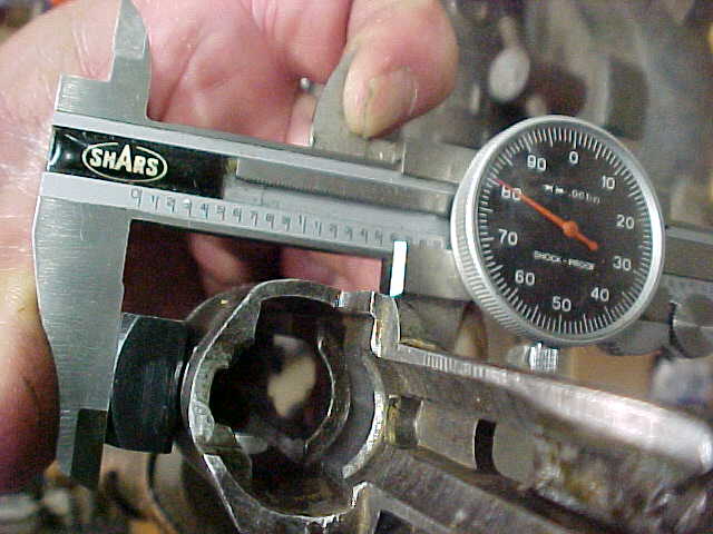
Here is a dial caliper, measuring the distance from the top of the mount to the bottom of the receiver. Note the 1.581 reading.
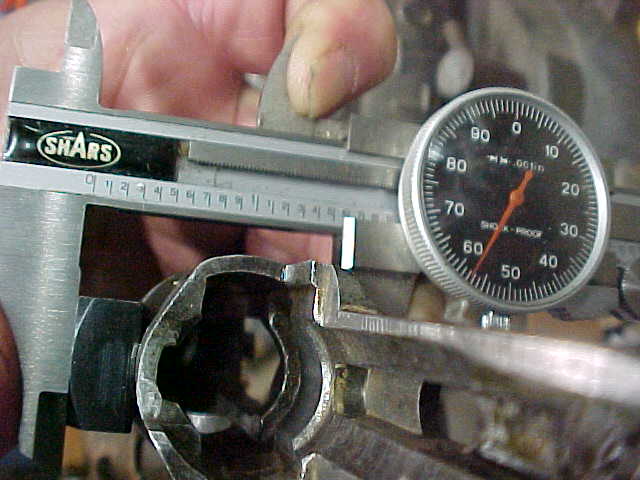
Here is the same set-up, but with the mount firmly against the receiver. See the 1.558 reading? This means that the mount was flexed 23 thousandths when the rear screw was installed. I don't like that, so I cut a 20 thousandths brass shim to fit between the mount and the receiver at the rear. Now here is where the real paranoia is revealed. After the base was shimmed and found acceptable, a line was scribed around the base, at the front and rear, on the receiver. Then the mount was removed and
the area inside the scribed lines was lightly ground. Then the ground area was "tinned" with solder,
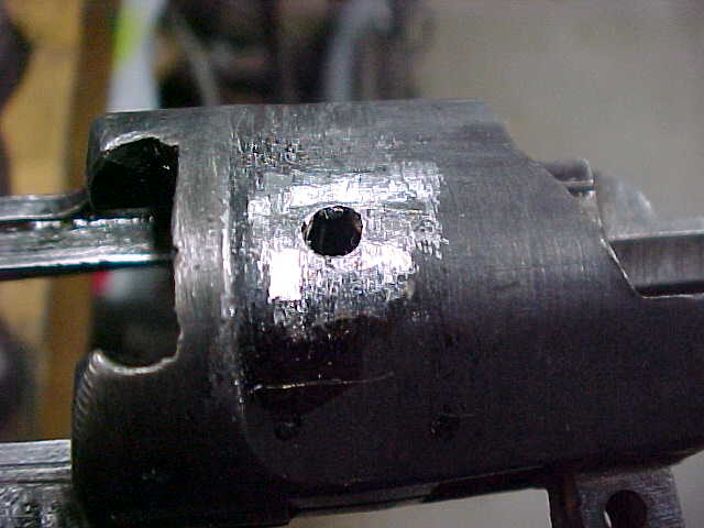
both the front and rear, the base was tinned at the front and rear, and the shim was tinned. Then the whole thing was remounted, with the three screws left loose, heated, additional solder added, the screws tightened while still hot, excess solder removed, screws tightened once more, and the whole thing left to cool. This is one base that should not shoot loose !!